Project Overview
Comfort Inn Hotel is a flagship hospitality project designed to offer a perfect blend of luxury and warmth. With world-class suites, fine dining restaurants, and expansive banquet halls, it caters to both business travelers and leisure guests seeking an unforgettable experience.
Floor Plans & Details
A comprehensive breakdown of the architectural layout, zoning, and design highlights across all levels.
1 / 2
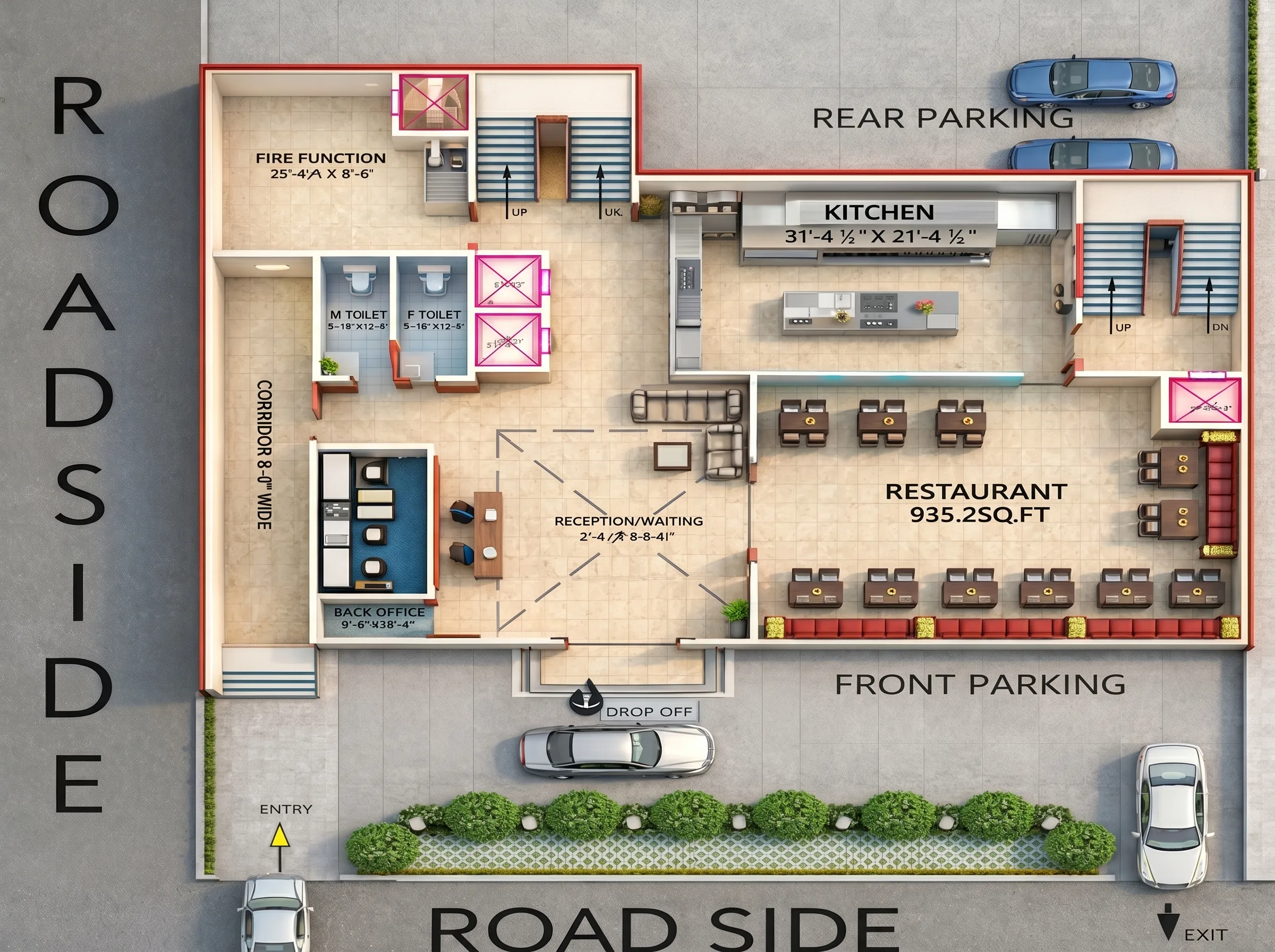
Ground Floor
1.Entry & Access
- Main entry from road side
- Dedicated Drop-off zone in front parking
- Separate Entry and Exit vehicular movement
- Easy pedestrian access to Reception
2.Reception & Waiting Lobby
- Centrally located for clear visibility
- Area: 27’-4½” × 27’-8½”
- Designed as welcoming space with seating
- Direct connectivity to: Restaurant, Corridor, Kitchen, Staircases
3.Restaurant Area
- Total Area: 935.2 sq.ft
- Flexible seating arrangement: Sofa seating along wall, 4-seater dining tables
- Direct access to kitchen
- Natural lighting from front façade
4.Kitchen
- Size: 31’-4½” × 21’-4½”
- Located at rear for service efficiency
- Separate internal circulation
- Close access to restaurant dining area
5.Pre-Function Area
- Size: 20’-4½” × 19’-0”
- Connected to staircase
- Suitable for waiting / small gatherings
6.Service & Support Areas
- Male & Female Toilets
- 8’-0” Wide Corridor for smooth movement
- Back Office (9’-0” × 20’-0”)
- Vertical Circulation: 2 Staircases (Up & Down), Lift Provision
7.Parking Layout
- Front Parking for visitors
- Rear Parking for staff/service
- Clear vehicular circulation path
Design Highlights
Functional zoning (Public & Service separation)
Smooth circulation with 8 ft wide corridor
Efficient kitchen-to-restaurant connectivity
Clear vehicular & pedestrian segregation
1 / 2
First Floor
1.Floor Overview
- Primarily designed for Guest Rooms
- Central Double Height Opening (Lobby Below)
- Efficient circulation with central corridor
- Vertical connectivity via: 2 Staircases (Front & Rear), 2 Lift Cores
2.Guest Room Configuration
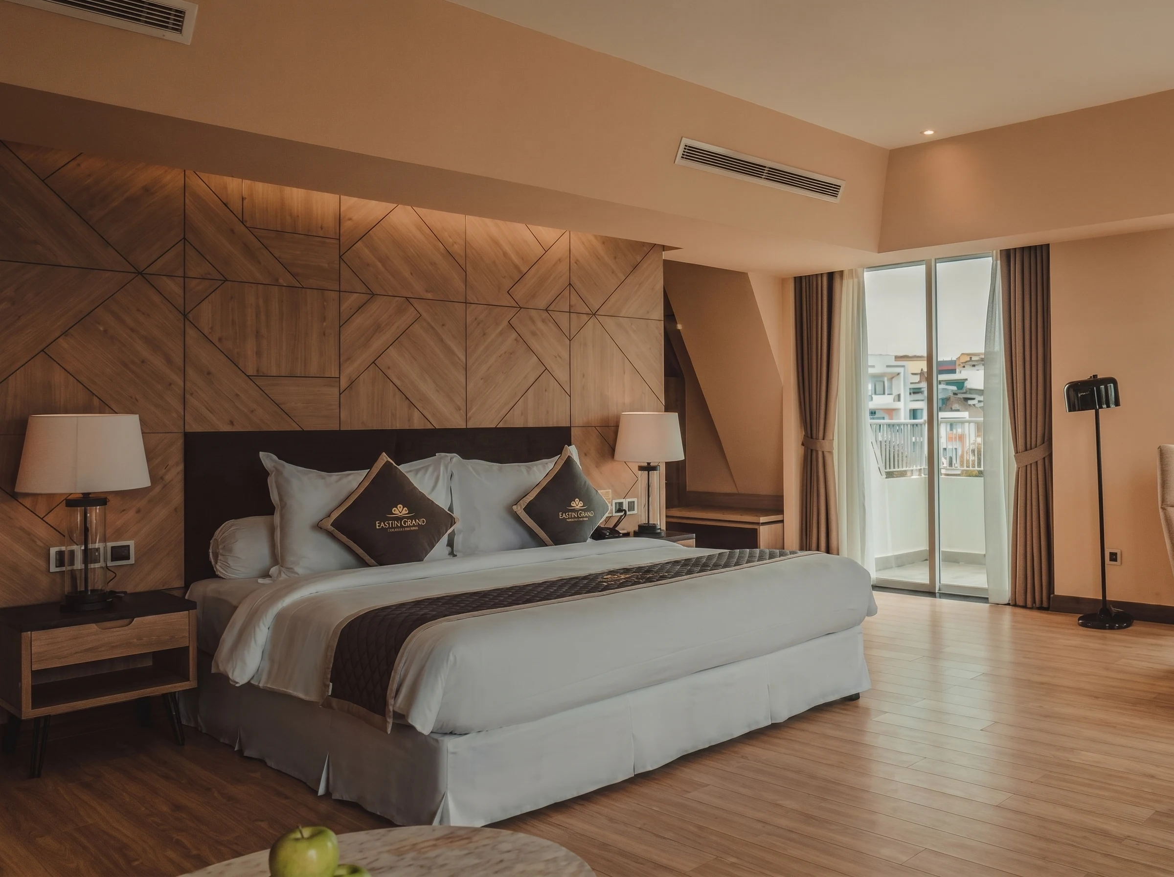
- Multiple Standard Rooms: 10’-0” × 14’-0”, 11’-0” × 14’-0”, 11’-8½” × 14’-0”
- 1 Larger Premium Room: 15’-3” × 16’-0”
- All rooms include: Attached Toilets, Wardrobe space, Proper ventilation & natural light
3.Toilets
- Standard Toilet Size: 5’-7½” × 8’-0”
- Larger Toilet (Premium Room): 9’-8½” × 6’-0”
- Efficient plumbing alignment for services
4.Circulation Planning
- Central Corridor ensures smooth movement
- Clear separation between Room access and Vertical circulation
- Balanced distribution of rooms on both sides
5.Vertical Circulation
- Staircase (UP/DN) at both ends
- Lift Core: Approx. 5’-8” × 5’-6”
- Direct connection to: Ground Floor Lobby (Double Height Visual Connection), First Floor
Design Highlights
Symmetrical room layout
Central double-height void enhances spatial quality
Efficient service alignment
Comfortable room proportions
Easy accessibility via lifts & stairs
1 / 3
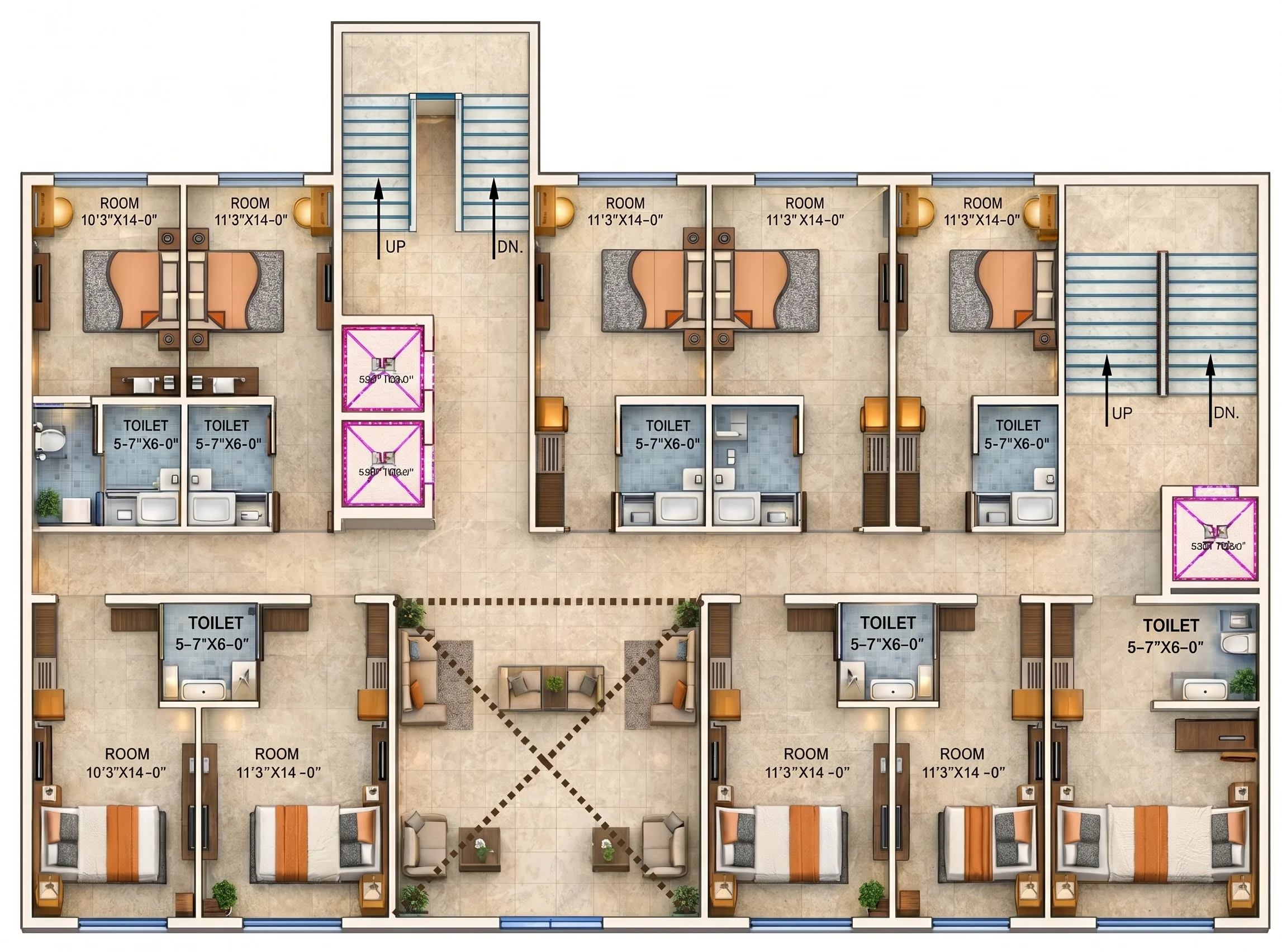
Typical Guest Room Floor
1.Floor Planning Concept
- Symmetrical guest room layout on both sides
- Central 5’-0” Wide Corridor
- Efficient circulation and privacy planning
- Vertical connectivity through: 2 Staircases (Front & Rear), Lift Cores
2.Guest Room Configuration
- Standard Rooms: 10’-0” × 14’-0”, 11’-0” × 14’-0”, 11’-8½” × 14’-0”
- Premium Room: 15’-3” × 16’-0”
- All rooms include: Attached toilet, Wardrobe space, Natural ventilation, Comfortable bed layout
3.Toilet Planning
- Standard Toilet: 5’-7½” × 8’-0”
- Premium Toilet: 9’-8½” × 6’-0”
- Back-to-back toilet layout for: Efficient plumbing, Reduced service shafts, Cost-effective construction
4.Circulation
- 5’-0” wide corridor for smooth movement
- Rooms aligned on both sides
- Clear zoning between: Private (Rooms), Semi-public (Corridor), Vertical Core
5.Vertical Circulation Core
- Lift approx. 5’-8” × 5’-6”
- Staircases at both ends
- Direct access to: Ground Floor Lobby (Double Height), Other Guest Floors
Design Highlights
Compact & efficient room layout
Optimized plumbing alignment
Balanced room distribution
Easy access & fire safety compliance
Functional hospitality planning
1 / 2
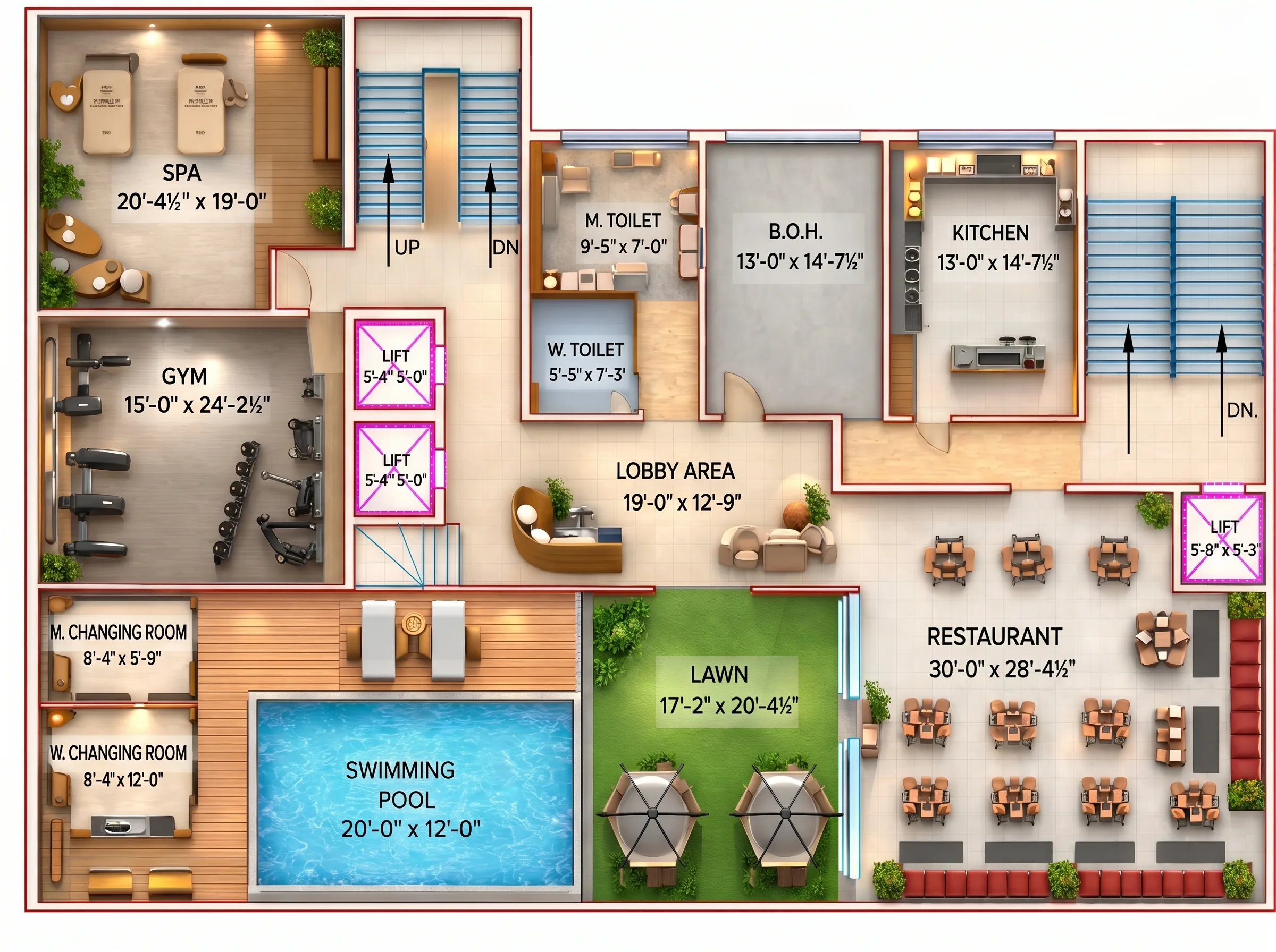
Rooftop
1.Floor Concept
- Designed as a Recreational & Leisure Zone
- Combination of indoor and outdoor amenities
- Segregation between: Public dining, Wellness facilities, Service areas
2.Wellness Zone
- Spa Size: 20’-4½” × 19’-0”, Located in a quiet corner for privacy, Connected through lobby
- Gym Size: 15’-0” × 24’-2½”, Spacious layout, Natural light and ventilation
3.Pool & Deck Area
- Swimming Pool: 20’-0” × 12’-0”
- Wooden deck seating area
- Male & Female Changing Rooms
- Designed for relaxation and open-air experience
4.Outdoor Lawn
- Size: 17’-2” × 20’-4½”
- Open green space
- Suitable for: Small gatherings, Evening seating, Rooftop events
5.Rooftop Restaurant
- Size: 30’-0” × 28’-4½”
- Indoor dining space
- Sofa seating + table layout
- Direct connection to service kitchen
6.Service & Support Spaces
- Kitchen: 13’-0” × 14’-7½”
- B.O.H (Back of House): 13’-0” × 14’-7½”
- Male & Female Toilets
- Lift & Staircase access
- Central Lobby: 19’-0” × 12’-9”
7.Vertical Circulation
- Lift access to rooftop
- Staircase for fire safety compliance
- Clear circulation between zones
1 / 2
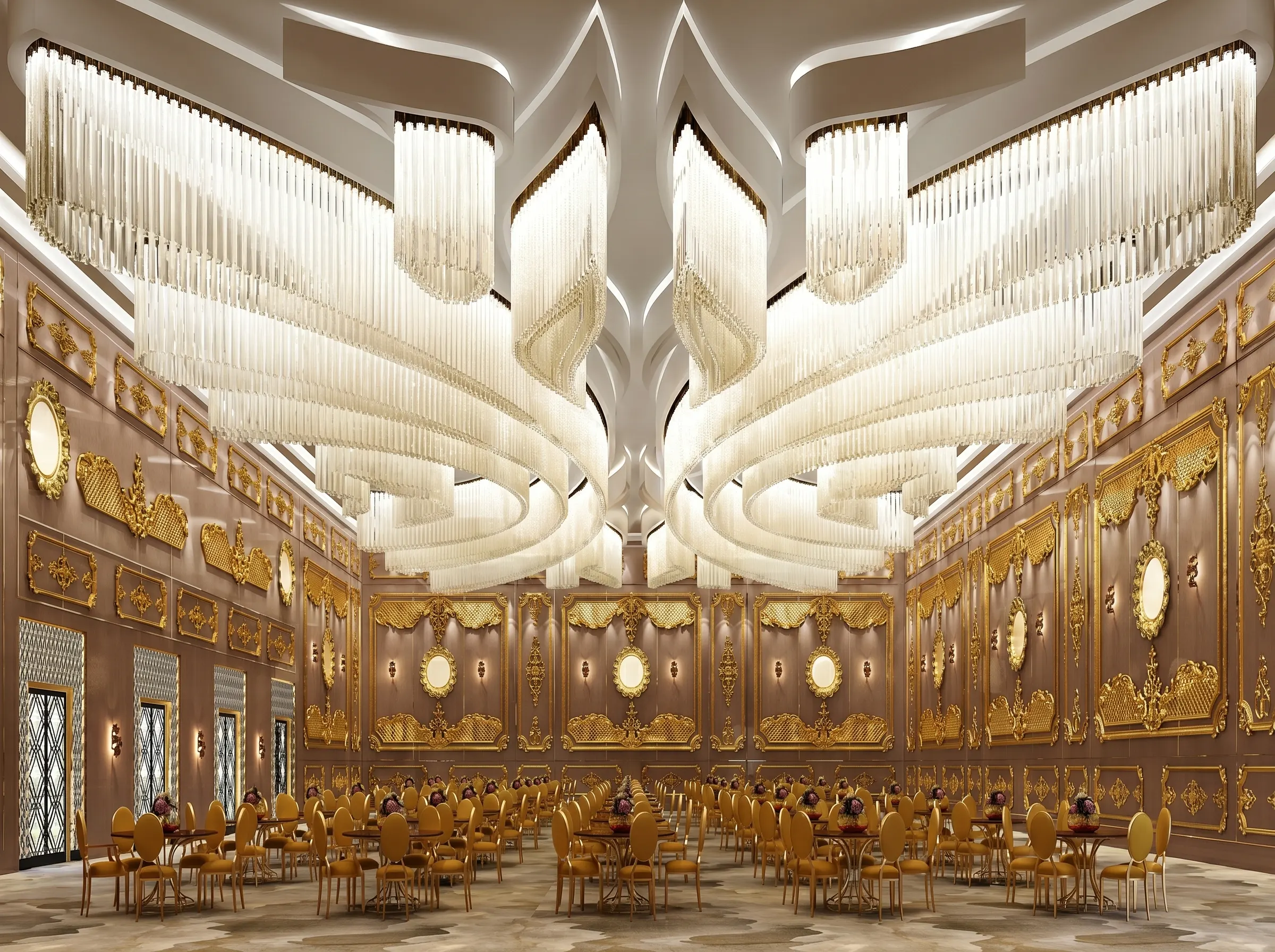
Basement
1.Floor Overview
- Dedicated Banquet & Event Space
- Separate service circulation
- Direct vertical connectivity to upper floors
- Designed for large gatherings & functions
2.Banquet Hall
- Total Area: 4247 sq.ft
- Flexible seating layout: Round table arrangements, Cluster seating
- Dedicated Main Stage Area
- Clear central space for: Weddings, Conferences, Corporate events
3.Buffet Planning
- L-Shaped Buffet Counter
- Strategically placed for: Smooth guest movement, Avoiding congestion, Easy access from kitchen & BOH
4.Pre-Function Area
- Size: 20’-4½” × 42’-0”
- Acts as reception/waiting space
- Buffer between banquet & circulation core
5.Kitchen & BOH
- Kitchen: 20’-0” × 18’-10”
- BOH: 48’-1” × 18’-10”
- Efficient service alignment
- Separate staff movement from guest circulation
6.Toilets
- Male Toilet: 6’-11” × 14’-9”
- Female Toilet: 6’-11” × 14’-9”
- Located near pre-function zone
7.Circulation
- 6’-0” Wide Corridor
- Lift access from basement
- Two Staircases for: Guest access, Fire safety compliance